
I recently installed a universal digital speedometer on my EX500 streetfighter build. This speedometer came in a box of parts included with my bike when I bought it, but it seems to be identical to many of the same models found on ebay and aliexpress, see the following link for example:
http://www.aliexpress.com/item/2016...cycle-MotorBike-F1-2-4-Cylinders/32622056831.html?spm=2114.40010308.4.92.tMCxdQ
.... You get the picture. There's a ton of these things for sale and they're dirt cheap. I was considering getting an acewell or trailtech gauge, but these things are a fraction of the price.
So far it seems pretty sweet. It's easy to read in a variety of lights, the tach seems accurate, the indicator/neutral/hi/lo lights all seem to work well. Also despite being a cheap ebay product, I've ridden in the rain a number of times and it hasn't fried yet!
The downsides: On a functionality front, it lacks an oil pressure warning and coolant temp gauge. I hooked up the fuel level gauge to the coolant temp wire from the bike's harness and the resistance is wrong so it reads incorrectly. I am working on finding the proper resistance to run to make it more accurately display coolant temperature. The speed is time averaged (as it should be) but the sampling time seems to be a bit large so there is some lag in changing the display.
From an installation point of view, it comes from china, with little to no instructions or technical support available. I tried contacting a seller on ebay for a wiring diagram or programming instructions and I got very broken instructions that appear to have come out of google translate. It also requires a custom mount, as well any other aftermarket speedometer, and you need to mount a hall effect sensor and magnets to get the digital speedometer to work.
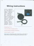
Wiring The Speedometer:
After finding a sample wiring diagram on an aliexpress sales page, as well as some trial and error, here is the wiring I came up with.
The first thing I did was clip the connectors off of the unit, as they don't fit the kawasaki harness anyways. I crimped on some butt connectors to play around with different wiring. I also removed the bike harness's gauge connectors and crimped on butt connectors. Leave the halll effect sensor connector as is, since you will want to use that later.
Speedometer:
Light Blue - Right Signal
Brown - Low Beam
Orange - Left Signal
Black - Ignition
Green/Black - Ground
Blue/White - Fuel Level (Connect this to the coolant temp line on the bike harness)
Dark Blue - High Beam
Purple/Black - RPM
Yellow/White - Neutral Indicator
Red - Connect this directly to the positive terminal of your battery. This is the "memory" supply to the unit. If you disconnect this, then all the settings that you program into the dash will be reset (ie. wheel circumference, odometer, etc)
The other wires are for gear indicators, which the EX500 is not equiped with. I clipped these wires and electrical taped them to keep them out of the way.
Bike Harness:
Blue with thin red stripe - Oil pressure light (this isn't able to be plugged into the gauge, so just cut it and tape it to the harness for the time being)
Dark Green - Left Signal
Grey - Right Signal
Red/Black - High Beam
Red with thin blue stripe - low beam (this is referred to as the "meter light" on the EX500 wiring diagram)
Light Green - Neutral indicator
Yellow/White - Coolant temperature
Green/white - tachometer
black/yellow - ground
Brown/White - Ignition
Once I confirmed the wiring configuration with butt connectors, I labelled everything, removed the connectors, and pinned a 10-Pin DELPHI connector. You can use whatever type of connector you want, I just had DELPHI parts kicking around so I used them. DELPHIs are waterproof but I really don't think it is necessary.
Mounting the Hall Effect Sensor:
Hall effect sensors work by varying it's output based on a magnetic field. They're used on all modern cars and motorcycles for speedometers, traction control, and so forth. Much like the trailtech vapor, this unit requires mounting the sensor near the wheel and installing two magnets which will pass by hall effect sensor.
The magnets that came with the speedo were set into brake buttons for floating disks (which the EX500 does not have) so I got some small magnets from the hardware store and JB welded them to the inner edge of the disk, just outside the mounting bolt circle. I mounted them 180 degrees apart. Make sure to test fit them for rubbing/interference before epoxying them in place.
As for mounting the sensor, I took a 1/8" thick piece of aluminum and drilled an M10 clearance hole, then a clearance hole for the sensor (don't remember the exact size - you can do this yourself). The brake caliper mount has an extra tapped M10 X 1.25 hole which I secured the bracket to. Make sure you loctite this. Now the sensor can be adjusted to an appropriate distance from the magnets to work. You can test it by propping up the front end of the bike and spinning the tire to see if it reads anything.
IMPORTANT NOTE: Before you mount your magnets, test them with the sensor to make sure you have them in the proper orientation. Hall effect sensors are polarity sensitive, so if your magnet is mounted backwards they will not work.
Programming the Speedometer:
Programming is simple - turn off the key, hold the button on the back, turn the key on. If you hold it for long enough, a different display will appear. This is the set up menu. The first three digits are half of the wheel circumference in millimeters. To shift digits, press and hold the button. I had to play around with this as it wasn't exactly what I calculated. I compared it to a GPS speedometer on my phone for a while to get it dialed.
The next digit is for fuel level resistance - 1 is for 100 ohm, 5 is 500 (only two options here). I used 5 but I still think it's wrong.
The last digit I've read can mean either number of cylinders.... or stroke. There are only two options: 2 or 4. Whatever it is, I used 4 and it seems to work fine.
Once you're done, turn off the ignition and turn it on again, it should work from there.
To switch between MPH and KMPH, hold the back button for a few seconds under normal operation.
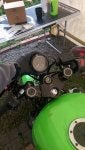
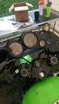
Mounting the Speedometer:
I measured the back of the speedometer up with my calipers and made a rough drawing for what the pattern should be. I made an aluminum bracket that is mounted to the bike between the upper triple clamp and the ignition switch. I milled mine and then bent it, but you could probably get away with a drill, a dremel and a hacksaw. There's a million ways to mount it to the bike so I'll let you work your own creative process on this.
Attached are a few photos of the gauge, the mount, a wiring schematic from aliexpress, and the old gauge for comparison.
I'll snap a few photos of the hall effect mount later and upload them.
Anyways, I hope this helps you all with your installation if you decide to get this gauge. It's pretty sweet and if you're a broke university student like me then the price speaks for itself. If you have any questions feel free to post them here.
- Ryan
http://www.aliexpress.com/item/2016...cycle-MotorBike-F1-2-4-Cylinders/32622056831.html?spm=2114.40010308.4.92.tMCxdQ
.... You get the picture. There's a ton of these things for sale and they're dirt cheap. I was considering getting an acewell or trailtech gauge, but these things are a fraction of the price.
So far it seems pretty sweet. It's easy to read in a variety of lights, the tach seems accurate, the indicator/neutral/hi/lo lights all seem to work well. Also despite being a cheap ebay product, I've ridden in the rain a number of times and it hasn't fried yet!
The downsides: On a functionality front, it lacks an oil pressure warning and coolant temp gauge. I hooked up the fuel level gauge to the coolant temp wire from the bike's harness and the resistance is wrong so it reads incorrectly. I am working on finding the proper resistance to run to make it more accurately display coolant temperature. The speed is time averaged (as it should be) but the sampling time seems to be a bit large so there is some lag in changing the display.
From an installation point of view, it comes from china, with little to no instructions or technical support available. I tried contacting a seller on ebay for a wiring diagram or programming instructions and I got very broken instructions that appear to have come out of google translate. It also requires a custom mount, as well any other aftermarket speedometer, and you need to mount a hall effect sensor and magnets to get the digital speedometer to work.
Wiring The Speedometer:
After finding a sample wiring diagram on an aliexpress sales page, as well as some trial and error, here is the wiring I came up with.
The first thing I did was clip the connectors off of the unit, as they don't fit the kawasaki harness anyways. I crimped on some butt connectors to play around with different wiring. I also removed the bike harness's gauge connectors and crimped on butt connectors. Leave the halll effect sensor connector as is, since you will want to use that later.
Speedometer:
Light Blue - Right Signal
Brown - Low Beam
Orange - Left Signal
Black - Ignition
Green/Black - Ground
Blue/White - Fuel Level (Connect this to the coolant temp line on the bike harness)
Dark Blue - High Beam
Purple/Black - RPM
Yellow/White - Neutral Indicator
Red - Connect this directly to the positive terminal of your battery. This is the "memory" supply to the unit. If you disconnect this, then all the settings that you program into the dash will be reset (ie. wheel circumference, odometer, etc)
The other wires are for gear indicators, which the EX500 is not equiped with. I clipped these wires and electrical taped them to keep them out of the way.
Bike Harness:
Blue with thin red stripe - Oil pressure light (this isn't able to be plugged into the gauge, so just cut it and tape it to the harness for the time being)
Dark Green - Left Signal
Grey - Right Signal
Red/Black - High Beam
Red with thin blue stripe - low beam (this is referred to as the "meter light" on the EX500 wiring diagram)
Light Green - Neutral indicator
Yellow/White - Coolant temperature
Green/white - tachometer
black/yellow - ground
Brown/White - Ignition
Once I confirmed the wiring configuration with butt connectors, I labelled everything, removed the connectors, and pinned a 10-Pin DELPHI connector. You can use whatever type of connector you want, I just had DELPHI parts kicking around so I used them. DELPHIs are waterproof but I really don't think it is necessary.
Mounting the Hall Effect Sensor:
Hall effect sensors work by varying it's output based on a magnetic field. They're used on all modern cars and motorcycles for speedometers, traction control, and so forth. Much like the trailtech vapor, this unit requires mounting the sensor near the wheel and installing two magnets which will pass by hall effect sensor.
The magnets that came with the speedo were set into brake buttons for floating disks (which the EX500 does not have) so I got some small magnets from the hardware store and JB welded them to the inner edge of the disk, just outside the mounting bolt circle. I mounted them 180 degrees apart. Make sure to test fit them for rubbing/interference before epoxying them in place.
As for mounting the sensor, I took a 1/8" thick piece of aluminum and drilled an M10 clearance hole, then a clearance hole for the sensor (don't remember the exact size - you can do this yourself). The brake caliper mount has an extra tapped M10 X 1.25 hole which I secured the bracket to. Make sure you loctite this. Now the sensor can be adjusted to an appropriate distance from the magnets to work. You can test it by propping up the front end of the bike and spinning the tire to see if it reads anything.
IMPORTANT NOTE: Before you mount your magnets, test them with the sensor to make sure you have them in the proper orientation. Hall effect sensors are polarity sensitive, so if your magnet is mounted backwards they will not work.
Programming the Speedometer:
Programming is simple - turn off the key, hold the button on the back, turn the key on. If you hold it for long enough, a different display will appear. This is the set up menu. The first three digits are half of the wheel circumference in millimeters. To shift digits, press and hold the button. I had to play around with this as it wasn't exactly what I calculated. I compared it to a GPS speedometer on my phone for a while to get it dialed.
The next digit is for fuel level resistance - 1 is for 100 ohm, 5 is 500 (only two options here). I used 5 but I still think it's wrong.
The last digit I've read can mean either number of cylinders.... or stroke. There are only two options: 2 or 4. Whatever it is, I used 4 and it seems to work fine.
Once you're done, turn off the ignition and turn it on again, it should work from there.
To switch between MPH and KMPH, hold the back button for a few seconds under normal operation.
Mounting the Speedometer:
I measured the back of the speedometer up with my calipers and made a rough drawing for what the pattern should be. I made an aluminum bracket that is mounted to the bike between the upper triple clamp and the ignition switch. I milled mine and then bent it, but you could probably get away with a drill, a dremel and a hacksaw. There's a million ways to mount it to the bike so I'll let you work your own creative process on this.
Attached are a few photos of the gauge, the mount, a wiring schematic from aliexpress, and the old gauge for comparison.
I'll snap a few photos of the hall effect mount later and upload them.
Anyways, I hope this helps you all with your installation if you decide to get this gauge. It's pretty sweet and if you're a broke university student like me then the price speaks for itself. If you have any questions feel free to post them here.
- Ryan


") .... just need to be creative with some fabrication skills)
.... just need to be creative with some fabrication skills)